Cite as: Stefanescu, D., 2020. Alternate Means of Digital Design Communication (PhD Thesis). UCL, London.
Previously in this thesis, the role of digital technology in communication and the effects of standardisation were discussed at a theoretical level. The AEC industries, as opposed to other design industries, are characterised by much less integrated environments in which actors are loosely coupled. The industry works on a project-by-project basis, and each project entails a different socio-technical network of contractors, sub-contractors, design firms and engineering offices. All these actors may change from one assignment to the next; even if consistency is possible, it is nevertheless not guaranteed. Design data, as such, is being produced and consumed by a diverse group of people, professions and organisations. As previously discussed, this context is fertile ground for the emergence of wicked problems. This is because even if shared values and concepts may exist, they are not guaranteed to be in place at the start of a design project. Or, for that matter, for the duration of the project itself. In the context of digital standards for design data representation, this places an onerous burden on correctly specifying a productive level of technologically imposed precision that still allows for a heuristic approach. The correct balance between predefined formal representations and organically emerging informal standards is difficult to define in a digital context; as discussed in Chapter 2, Design and Communication section, a technical approach to communication tends to marginalise the semantic aspects of the process.
To a certain extent, this chapter asks whether one can sketch with digital representations of design data. Traditional means of design representation, such as models, sketches, plans, etc., encode design information in such a way that they deliver a certain meaning to the receiver. This meaning is not always quantifiable: for example, aesthetic qualities that can be evident in a hand drawn sketch—such as texture, material, spatial qualities—can be completely lost in a digital three-dimensional model. Such methods achieve this by speculating their medium and the context in which they are decoded and encoded to guide the receiver in inferring a certain meaning. The actors involved in the design process may not share the same internal representations of a specific building element. For example, an architect may represent a beam in one way, whereas the structural engineer in a different way. By virtue of these two persons using their own specialised software, in a digital environment, ontological difference between expert systems (domains, professions, or organisations) is a fact cemented by a technical and political reality defined by software vendors. Furthermore, the problem is compounded by the fact that, for example, an architect will evaluate a beam from an aesthetic point of view, whereas an engineer from its performance standpoint: different definitions of the same object are coupled with different notions of value.
At a purely technical level, Eastman et al. suggest that there are two major avenues for ensuring interoperability in the AEC software world. The first one is to stay within the ecosystem of software tools provided by only one vendor, for example Autodesk or Bentley Systems (Eastman et al., 2008, p. 18). This, in theory, ensures the compatibility of all the products within that specific software “suite”. The main advantage of this approach is that it allows for “tighter and easier integration amongst products in multiple directions”, for example changes can be propagated across mechanical, architectural and engineering models. The second approach relies on standards that define building objects. The Industry Foundation Classes (IFC) object model positions itself as the official interoperability standard of the AEC industry, and has been in active development since 1994 (Froese, 2003; Plume and Mitchell, 2007; van Berlo et al., 2012). It is widely used throughout the whole design and build process and underpins most, if not all, BIM techniques, regulations and practices. IFC classes aim to specify a complete vocabulary of all elements (both high level—walls, doors, etc.—as well as low level—points, lines, etc.) that are used in architectural design, engineering and construction (Hamil, 1994). While the “universality” of IFC as a standard is recognised throughout the industry, its actual implementation within the competing CAD software packages is anything but. Software vendors rely on custom specialised features to differentiate themselves, thus framing a conflict of interest between the needs of their users and their own business survival. Consequently, this has resulted in incomplete and inconsistent implementations of the IFC specifications throughout the CAD software industry that negate the benefits that come from standardisation: because of differences in how IFC data is produced and consumed, its reliability is compromised.
Because of these frustrations, and coupled with the fact that the design process becomes more and more digitalised and data-oriented, many engineering and design companies have been developing in-house alternative design data exchange standards positioned as internal replacements for the official IFC standard, rather than as additions or extensions. These replacements aim to better suit their own need and have applicability scopes that vary from a single-project base to a company-wide norm. The emergence of such standards results from the need to further articulate domain- and organisation-specific knowledge that accumulates over time: most observed examples underpin computational techniques, workflows and methodologies that quintessentially represent a given organisation market advantage, or a given domain’s internal language constructs that allow for its effective functioning (Giddens, 1991; Kuhn, 1962). As reflected in Chapter 2, Literature Review, communication is an inferential process during which the cognitive processing of the communicants tends to be minimised—which is a fundamentally dynamic process in direct conflict with the rigidity of a standard. Consequently, one can argue that the emergence of other object models describing specialised subsets of the objects that compose the built environment is a recurring natural phenomenon of ontological revision.
In the field of computer science, the development and increasing adoption of self-describing structures for object representation, such as JSON, enable alternative and more expressive ad-hoc “object models” to be defined. These allow for the representation of information to evolve throughout time easily in a coupled way with its implementations in various consuming applications. At the same time, they allow for the crystallisation in given patterns once a consensus, or balance, is reached. This chapter investigates if a similar approach to data representation is valid within the AEC industry: abstract enough to allow for the encoding and decoding of multiple ontologies, flexible enough to facilitate their revision and their combination, and thus supporting the emergence of shared meaning and understanding at a representational level.
4.1 Composable Data Structures
Throughout the course of this research project two different approaches have been experimentally enabled and assessed. The first approach, namely that of composable data structures, started on the assumption that all the potential elements of the built environment can be ultimately reduced to and defined by a standard set of geometric objects—points, lines, circles, polylines, etc.—and the usual programming language primitives—booleans, numbers, strings. Furthermore, this approach does not carry the assumption that one is able to predict in which way end users compose them (or relate to each other, or structure them internally) into higher level design objects such as walls, beams, columns, doors, etc: each of these higher-order ontological definitions, while similar at a superficial glance, can hold different meanings and internal representation structure depending on the domain that they are interpreted. For example, as mentioned above, a beam is a volumetric object for the architect, but a one dimensional line for the structural engineer. Similarly, one cannot know what properties a wall element will be best described by: it can be represented by a centre line, height and width for the purpose of spatial design; or it might be represented as a purely volumetric element for the purpose of costing; or it might be represented as an assembly date, a delivery date and site storage information if it is a prefabricated element. In a multi-disciplinary context, these object definitions can have partially shared properties, but their overall consistency is not guaranteed as the project evolves.
4.1.1 Implementation
In order to test this approach, a set of basic geometric object primitives were specified using the OpenAPI language. Subsequently, these were implemented in the .NET (C#) framework in order to be embedded in existing CAD applications environments. Specifications are formal descriptions of the requirements that an implementation needs to meet. Subsequently, the implementation itself can be enacted in any number of programming frameworks as long as it meets the requirements of the specification it is based on. This is relevant because one cannot assume a common programming environment shared by the digital software tools that produce and consume design data. While an assumption as to the fact that they may share, to a certain extent, basic definitions of geometric primitives (e.g., a point will be defined by three coordinates, a line by two points, etc.), the various software used in the industry are built on top of different code platforms (e.g., Rhinoceros 3D is based on the .NET framework, whereas SketchUp can be extended via Ruby).
The deciding factor in choosing the OpenAPI framework as a base in which to write the specification, against EXPRESS, RAML and API Blueprint or others, was based on several facts. First, it can be used to specify both server protocol implementations (which allowed us to have one specification document for the entirety of the Speckle platform) as well as client implementations. Second, compared to the other alternatives, OpenAPI specifications benefit from a wider range of tooling that can generatively scaffold said implementations, thus partly automating the process of writing code and simultaneously ensuring consistency across said programming environments. Finally, the community and overall project health of the OpenAPI framework is generally perceived as lending it good outlook in terms of future continuity and support.
Consequently, Speckle, implementing the composable data structures approach, allows for object definitions that can be arbitrarily extended and composed by the end users. “Arbitrarily” signifies the ability to continuously inform and adapt the definition of a given design element to the various ontologies of the actors interacting with said element. This is achieved, at a higher level, by allowing users to add semantic triples (Cyganiak et al., 2014) to the basic set of predefined object primitives mentioned above. A semantic triple codifies the relationship between two entities in the form of “subject – predicate – object” expressions, thus expressing informational relationships in a machine and human readable way. For example, one can codify the definition of a structural beam object by specifying its end point, start point, structural type, restraints and loads, or as well by its axis line, orientation and section property if the latter definition is better suited than the former to the task at hand.
Using dot notation to express the above, one can define such a triple as: myBeam.startPoint = myStartPoint. In this example, myBeam is the subject, startPoint is the predicate and myStartPoint is the object. Dynamically typed languages, such as JavaScript or Python, allow for the dynamic creation of such triples on any object without them being defined on its base class. Nevertheless, statically typed languages, such as C#, do not easily allow for this behaviour. Consequently, in the specification and subsequent implementation of the base geometry and primitive classes, the technical implementation opted for a compromise whereby custom properties can be defined inside a designated field named properties. This specific field can then be implemented as a specific dynamic structure native to coding framework itself (e.g., in JavaScript, it will be simply another default Object, as all objects are key-value pairs, whereas in C#, it will be implemented as a Dictionary<string, object>, which is one of the key-value pair primitives offered by the language.
The list of primitives that have been defined throughout the course of this project, at the time of writing, comprises the following 20 types: Boolean, Number, String, Interval, Interval2d, Point, Vector, Plane, Line, Circle, Arc, Ellipse, Polyline, Curve, Polycurve, Box, Mesh, Extrusion, Brep, Abstract[11].
This set of object types can be split into two categories, namely (1) primitives in the classical understanding of computer science – specifically, boolean values (true or false), numbers (defaulting, in practice, to the programming language’s implementation, otherwise a double-precision floating-point format, occupying 64 bits of computer memory) and strings (UTF-8 encoded); (2) basic mathematical constructs used extensively in computational geometry, specifically one- and two-dimensional intervals, vectors and planes; and (3) actual computational geometry primitives, namely lines, circles, meshes, etc. While the internal definitions of these objects have evolved in time driven by user needs, the actual set was chosen based on the fact that most used authoring software supports them either as first-class objects, or as supporting types underpinning higher level objects. For example, Grasshopper and Dynamo have the concept of one- and two-dimensional intervals, which is used in surface subdivision computations; Revit, while having an XYZ construct representing a Point, does not natively support them as document objects – they are used exclusively in scaffolding the basic shape and form of higher level objects, such as Walls, AdaptiveFamily, etc.
[{
  "$ref": "#/definitions/SpeckleObject"
},
{
  "type": "object",
  "properties": {
    "type": {
      "default": "Mesh"
    },
    "vertices": {
      "type": "array",
      "items": {
        "type": "number"
      }
    },
    "faces": {
      "type": "array",
      "items": {
        "type": "number"
      }
    },
    "textureCoordinates": {
      "type": "array",
      "items": {
        "type": "number"
      }
    }
  }
}]
Figure 8: Above: the specification entry for the Mesh geometric primitive. Below: the implementation in C# of the Mesh class, automatically generated from the specification above.
public partial class SpeckleMesh : SpeckleObject
{
  public override string Type { get => "Mesh"; set => base.Type = value; }

  public List<double> Vertices { get; set; }

  public List<int> Faces { get; set; }

  public List<double> TextureCoordinates { get; set; }
}
Each of these objects have their own internal properties that describe its structure in a minimal way, and they share a set of common fields. The most important of these are objectId and hash: two equivalent object identity mechanisms, both used in the persistence and classification layer discussed in Chapter 5, Data Classification, as well as for purposes of data deduplication and diffing which are discussed in Chapter 6, Data Transaction. The former, objectId, is generated exclusively by the persistence layer (the logic and hardware pertaining to data storage from a software project), whereas the latter, hash can be generated both at the application layer (the part of a software project concerned with “business logic”) as well as at the persistence layer, only if it is not present. This is because, while the hashing algorithms used are the same (MD5), the availability of data from which to compute an accurate hash is lower at the persistence layer.
The hash property, essentially, represents a unique string that is specific to a given object’s sate. For example, a point object defined by [ 0, 0, 0 ] (hash = 13e81f6567b656a19c629377c7f5a698) will have a different hash if its coordinates are changed to, for example [ 1, 0, 1 ] (hash = 53ed8181875a36311d34ba1b5b46ff29). The hash is generated by passing the object’s byte array footprint from the computer’s memory to a standard hashing function, namely MD5. The resulting byte array is then converted to a hexadecimal string. The role of a hashing function is to map arbitrarily sized data to fixed size values. MD5, while proven to be cryptographically insecure, is a suitable choice given its efficient implementation on numerous platforms, low collision rate[12], and given that it is not used in this context for cryptographic purposes.
These class definitions were grouped under the name of SpeckleCoreGeometry. Several other complementary assemblies were developed to facilitate the encoding to and from the various CAD applications, namely Rhino, Grasshopper, Dynamo and Revit. Specifically, they facilitated the low level translation between the data representation of, for example, a Rhino Mesh object and a Speckle Mesh object, or a Dynamo Point to a Speckle Point. These assemblies dynamically extend the original object model with conversions methods that were as well dynamically loaded at runtime, thus allowing for injecting at runtime the correct dependencies in the host application itself. As such, when the Speckle plugin would be loaded by, for example, Dynamo, an end user would be able to access a ToSpeckle() method on all Dynamo geometry primitives that are supported, and a ToNative() method for all Speckle primitives that can be translated, or cast to native Dynamo objects.
4.1.2 Applications
Throughout the duration of this research project, the affordances offered by the composable object model approach described so far were used often to customise and enhance the digital data exchanges between the various sub problems of a given design task. For example, in a multidisciplinary team working on a façade project, the architectural stakeholders would use rectangular polyline-based definitions for the glass panels. The structural engineers would subsequently expand the object definition of a façade panel to contain various analysis results, such as end reaction forces on the four structural nodes. Nevertheless, these were used internally in their design process to size structural elements. When the resulting data was being fed back to the architects, the definition of a façade panel mutated again: the structural properties were partly replaced by a different set of properties, this time reflecting the volumetric properties of the newly designed structural support members as well as the tolerances and offsets needed for each particular panel.
Furthermore, composability opened the possibility of merging together multiple object-models. In other words, it allowed end-users to combine one object model with another one. For example, consider the representational definition of a structural beam, one useful for analysis purposes—centre line, loads, degrees of freedom of connection points—and a separate, product representation that would be fit for construction and logistical evaluations. Both these definitions could come from different object models, each defined by a specific stakeholder group, nevertheless they could coexist within the same object. These composite objects have the possibility to share basic traits, if a common set of properties is present.
Paul Poinet, a fellow InnoChain researcher, has advanced in this direction by creating a user interface that allows for the arbitrary construction of relationships between objects directly in Rhino, as well as adding custom, user defined properties (Poinet et al., 2018). Furthermore, his experiments with multiple-schema objects—involving a beam defined simultaneously from an engineer’s point of view, using an object model developed by a structural engineering company, and from a fabricator’s point of view (Figure 9)— demonstrated the potential of this approach to bridge information and meaning across domains of expertise.
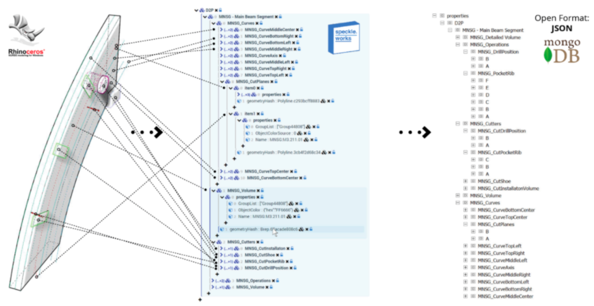
Figure 9: The construction of multi-schema objects in the parametric modelling software, Grasshopper. Reproduced with the permission of the author (Poinet et al., 2018).
By allowing users to interactively compose higher level objects based on a low-level schema, this approach distances itself from the rigours of a standard, and, most importantly, encourages dialogue to emerge between the actors involved in the communication process. The diagram below shows such a scenario (Figure 10): an actor (Mary), in Context A, creates a specific type of object, namely CustomObject_A and transmits it to a different actor (Alex) in Context B. Nevertheless, Alex does not share the same definition of that specific object as Mary does; or either he might need, for his purposes, to add, remove or combine properties of CustomObject_A in various ways to suit his own speciality, thus creating a new derived object type, namely CustomObject_B. This process can be repeated, with Alex further revising his object definition in a different context, for instance Context C, where different key-value pairs can be added or removed dynamically to better match the internal representation of the object with the ontology of the specific domain, or task, within which it is embedded. An example of such a customised object is shown in Figure 11, where the default properties are highlighted against the ones added by an end-user.
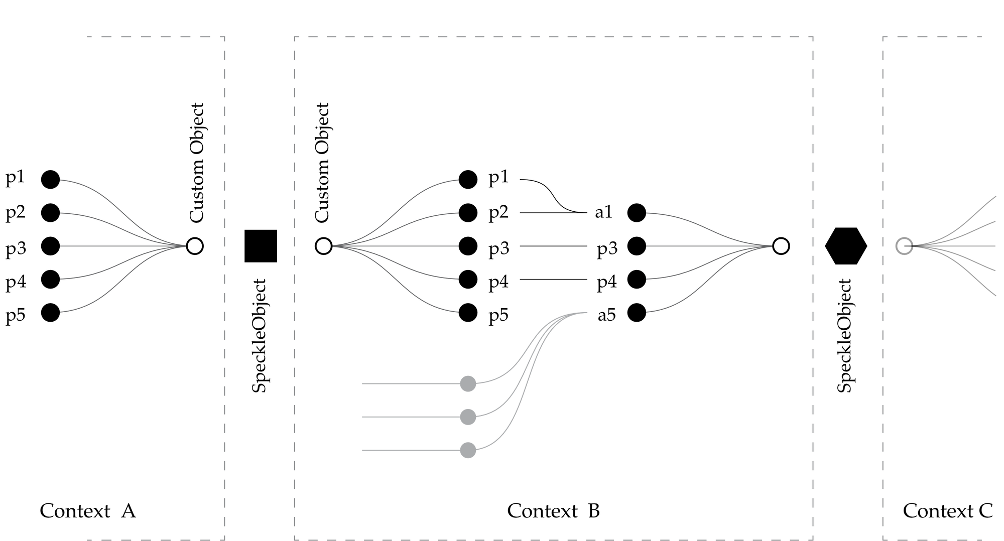
Figure 10: Ontological revision process: objects can be packed, unpacked and re-defined in various contexts by their users.
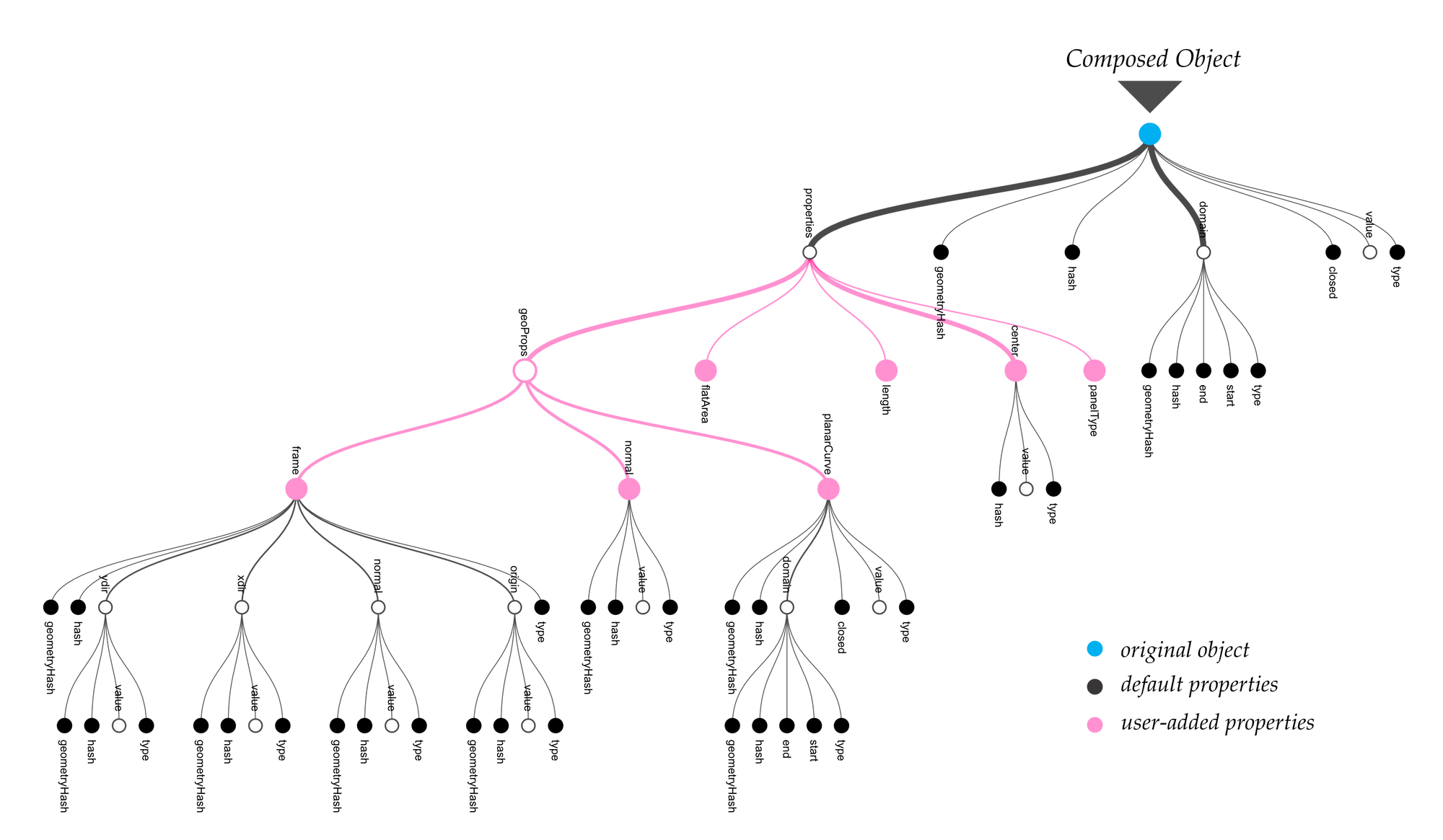
Figure 11: Example diagrammatic representation of user defined objects.
4.1.3 Affordances and Limitations
One of the major limitations of the composable data structures approach is the fact that there is no evident way to instrument this behaviour globally, across the various CAD software used by the AEC industry. This is because there is a tight coupling between the affordances of the user interface, software environment, and the actual process needed for composing new, higher-level objects. Within an WYSIWG environment, such as direct modelling in Revit, or Rhino, exposing such a functionality would require a large investment in the development of the user interface that would enable end users to employ it. Nevertheless, visual programming environments, such as Grasshopper and Dynamo, allowed us to instrument this process of object definition based on ontological revision by developing custom components that facilitated the process of adding, removing, and nesting user-defined key value pairs.
In this specific context, a composable object model proved to be an extremely productive vehicle for ontological revision. Specifically, by allowing end-users to freely exchange, combine and create temporary new ontologies as dictated by their need, the domain specific processes were better and more efficiently served. Essentially, a composable object model allowed for linkages between two, or more, separate domains to mutate over time, and thus build up and evolve a shared set of digital representations of design data.
4.2 Encoding Existing Ontologies
This section tackles the issue of existing object models and can be referred to as an attempt to explore whether the flexibility of the composable approach described above can be programmatically retro-fitted to existing well-defined schemas. As opposed to defining object ontologies “on the fly”, whereby end users create and evolve a glossary of building elements or concepts that is informal, or in other words not formally recorded in a central place, many AEC companies and organisations have created object models that encode pre-defined ontologies in a formal, centralised manner.
The most known is the IFC standard, the development of which is the purview of BuildingSmart International, a consortium of software development companies as well as industry representatives. During the course of this research, other object models developed internally within the various industry partners that this project attracted were observed[13]. Amongst these there are BHoM (The Buildings and Habitats Core object Model, 2019), Pegasus and DesignLink (Holzer and Downing, 2010). These object models, much smaller in size and ambition, were developed primarily to resolve the issues of interoperability that the IFC standard did not solve due to its fragmented implementation. As such, they were limited in their overall vocabulary, but efficient in solving the problems for which they were designed and streamlining the data exchanges that underpinned their authors’ design processes.
The original experiment with composable object models was well received by the project’s industry partners. Nevertheless, given their reliance on previously developed object models that already structured data in a way that facilitated their design and analysis processes, it was important to investigate whether existing schemas could be programmatically supported by dynamically translating them to use the same triple mechanism that was employed by the composable approach. Consequently, this section looks at the affordances and limitations of encoding and decoding an existing well defined object model to and from the composable object model described in the previously.
4.2.1 Implementation
As all of the object models that were accessible from the living laboratory context were based on the .NET framework and ultimately compiled to assemblies distributed via dynamically linked libraries (dll), the following technical implementation is similarly applicable only in the mentioned programmatic context. At its core, the implementation relies on the ability to reflectively inspect the properties (or fields) of an object of any type without being aware of its class definition (its specification), which is present in its original, potentially locked down, assembly. The basic object schema definitions, described in the previous section, were extended so as to contain a new type of object (SpeckleAbstract) which would specifically be able to host the information from any existing object. First, its properties and their values, broken down into the primitives that underpin the programming language, will be stored in the properties field, similar with the case for custom user-defined fields on base objects. Second, the name of the original schema from which the object came from, will be stored in a special, hidden field (_type) in a .NET framework specific format.
The process of creating a dynamic object out of a predefined one is as follows: for a given object, retrieve its existing public properties. For each of these properties, check whether the value of the property is a primitive object (boolean, number, string, or any of the geometric primitives defined). If this condition is satisfied, then create a new triple (key-value property) in the SpeckleAbstract’s properties dictionary with the key being equal to the original’s object property name, and the value being the one extracted from its instance. If the value does not meet the primitive object criterion, and thus is a different sub-object, create a new key-value property, with the key being equal to the original’s object property name, and set its value by repeating the process described, but applied on the sub-object.
public SpeckleAbstract EncodeAbstract( object myCustomObject )
{
  var mySpeckleAbstract = new mySpeckleAbstract();
  mySpeckleAbstract._type = myCustomObject.GetType().GetAssembly().Name;
  foreach( var property in myCustomObject.GetType().GetProperties() )
  {
    var myValue = property.GetValue()
    if( myValue is Primitive )
      mySpeckleAbstract.properties[ property.Name ] = myValue;
    else
      mySpeckleAbstract.properties[ property.Name ] = EncodeAbstract( myValue );
  }
  return mySpeckleAbstract;
}
Figure 12: (Code block) Pseudo-code implementation of the encoding method for a SpeckleAbstract object.
Figure 12 shows a pseudocode rendition of the encoding method. The actual implementation[14] is much more complex, as it needs to handle various specific cases – specifically, instances of properties that are lists (IEnumerable) or dictionaries (IDictionary), but as well potential recursive references. Furthermore, because the creation of this object is done programmatically, and not by invoking a constructor, its hash is also set by generating it from the object’s binary representation, extracted from its memory footprint.
4.2.2 BHoM & Pegasus
Buro Happold, an InnoChain industry partner, has been developing its own internal set of computational tools to standardise and speed up internal processes of design and analysis. These tools are grouped under the name of BHoM. It consists of an object model containing definitions for various classes that describe categories of objects grouped under various categories depending on their use case (Geometrical, Acoustic, Structural, Architectural, Planning, etc.—there are a total of approximatively 273 classes and interfaces). These comprise an evolving ontology that allows for the standardisation of the company’s digital processes across multiple software packages. In short, BHoM can be seen as an extensible object model which underpins the internal processes of interoperability and specialised computation. It allows users to employ various specialist software in a platform-independent way by assembling digital analysis workflows in a set of pre-existing parametric modelling user interfaces, such as Grasshopper and Dynamo.
Dialog, an engineering and design company with offices around North America, have been integrating Speckle at the core of their digital processes. Similarly to Buro Happold, they have also been developing a set of internal software tools that automates and unifies their analysis processes. These set of tools revolve around a core object model, namely Pegasus, and various integrations with other CAD/CAM software packages, such as ETABS, Robot, Rhino, Unity, etc.
During the course of this research project, they relied on Speckle’s compatibility with existing well defined schemas to be able to transfer data between the application clients that they have developed to match their internal processes. Dialog pursued an independent, parallel effort to that of Buro Happold because, at the time, BHoM was not yet released to the public, or open sourced. Nevertheless, the relevant differences between the two object models are minor – they were strikingly similar as they were created to cater to similar engineering needs. In the descriptions that follow, BHoM is the primary reference implementation, but the same analysis and reflection can be applied to Pegasus.
The architecture of BHoM’s codebase is well defined: object definitions are logically separated from operations that execute actual computational work on them. Furthermore, BHoM object definitions follow a simple and clear inheritance and composability pattern, and have an ideal depth of inheritance and class coupling index – both fitting within what is accepted as “good practice”. This allowed us to assess the viability of Speckle’s serialisation (encoding) and deserialisation (decoding) routines in handling Buro Happold’s object model.
As an experimental setup, a Bar object, from the BHoM’s structural elements object model subsection, is programmatically instantiated. This element is composed of two nodes (start and end points) and several other classes and enumerations. It does not contain any circular references, and neither have any direct translations routines to SpeckleObjetcs been added—there is no special conversion routine employed. Its diagrammatic representation as a SpeckleAbstract object is shown below (Figure 13), and its full composition revealed.
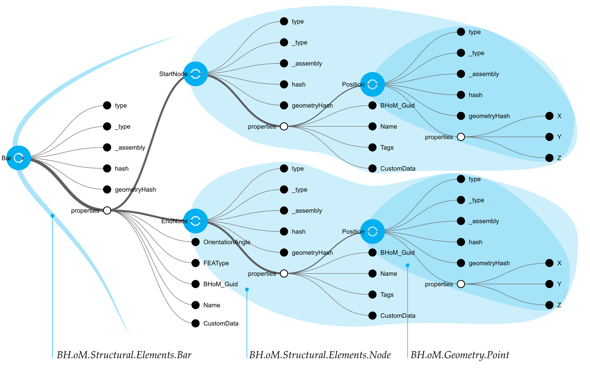
Figure 13: A graph showing the intermediate representation of a BHoM Bar object, as it was cast into a SpeckleAbstract DTO.
Within a context where there is access to the BHoM package, the deserialisation routine performs as expected: it is able to convert the resulting composite SpeckleAbstract object into its native BHoM object type (Bar) and its subcomponents (Node and Point), without any loss of fidelity. The same is achieved for all other tested object types; the verification methodology is to serialise the original object, deserialise it and then re-serialise to a SpeckleObject and check if the generated unique object hashes match.
The BHoM schema is user extendable and there are scenarios where circular or linear references are possible. For example, for the sake of convenience, the following scenario is envisioned: the GSA analysis software defines structural elements by their direct spatial coordinates, and therefore the author of the information adds direct references to them in order to have easier access without nesting. Consequently, the handling of linear references is tested by adding a set of custom properties to the Bar that reference some of its internal parts, namely EndNode, StartNode, and their respective Location properties. A diagrammatic representation of the resulting SpeckleAbstract object is below (Figure 14).
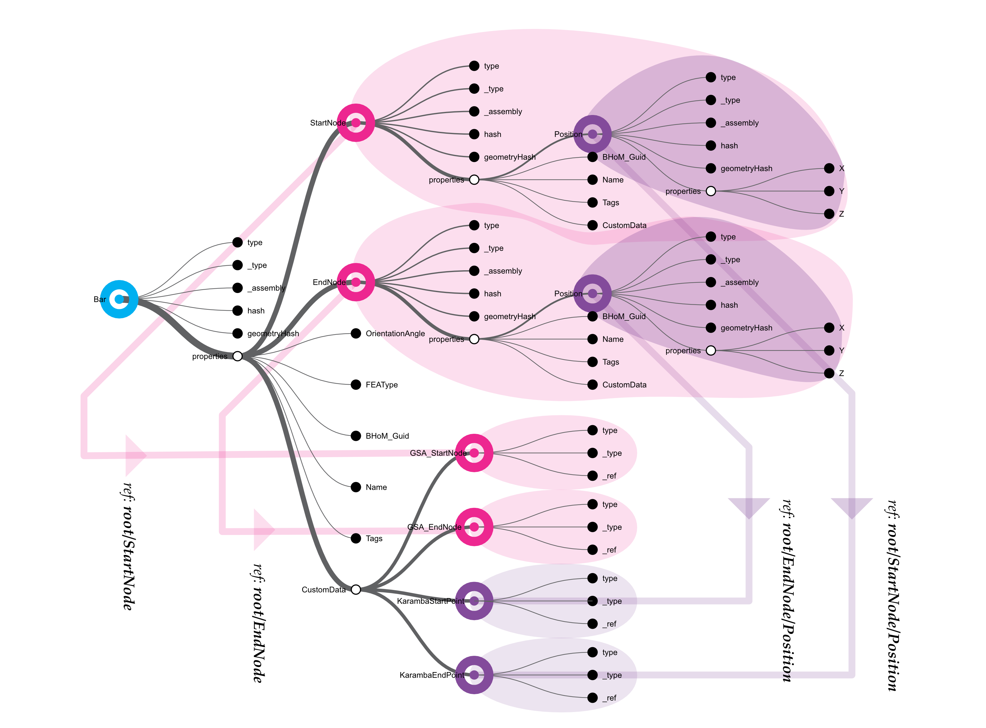
Figure 14: A diagrammatic representation of the reference tree of a given BHoM Bar object. The black circles represent object properties, the large grey circles represent embedded objects, and the arrows indicate nested references.
As the diagram above shows, the serialisation routine correctly identifies them and instead of copying the objects, sets a reference to the originals. Upon deserialisation, these are linked back to the newly created internal objects.
A recursive reference can happen if a sub-object contains a link to its parent object. For example, consider a set of Nodes that each have reference to their parent Bars. A corner node can thus reference two different Bars. Similarly, the Bar object holds two references to two different Nodes, which, in turn, reference their Bar. This can lead to cases in which, when serialising an object, if it has a large dependency tree, the routine may end up failing due to a too high recursion depth. The diagram on the left in Figure 15 illustrates such a potentially dangerous scenario, whereas the one on the right illustrates a “benign” case.
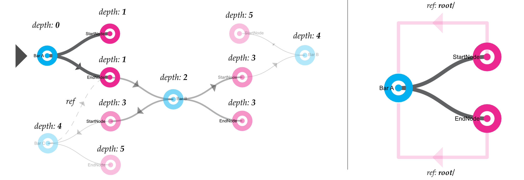
Figure 15: Diagram showing a generalised case of recursive references with a given object. Left: deeply-nested references; Right: simplified example, showing the child nodes directly referencing their parent.
In order to prevent endless recursion, the encoding routine for SpeckleAbstract objects stops at a stack depth of eight[15]. This results in the fact that objects that are too deeply nested into each other will not get serialised. This places an onus on the end users and, most importantly, developers to ensure that a more atomic structural model is observed[16].
4.2.3 GeometryGym IFC (ggIFC)
GeometryGym provides a vendor independent implementation of the IFC object model that works with a number of software packages, namely Rhino, Grasshopper, Revit, Tekla, etc. It is one of the most widely used interoperability solutions that is not bound to one software ecosystem or another. With the help of Jon Mirtschin, the author of the ggIFC toolkit, this section investigated the potential for IFC objects to be successfully encoded and decoded using the “schema-agnostic” strategy.
Initial tests show that, because of the way the IFC schema is specified and subsequently implemented, serialising one object will result in capturing an extremely long dependency chain of inter-related objects. If one suppresses the maximum serialisation recursion depth, it will essentially amount to the whole “file”. This is because any IFC object contains a chain of references that point to an IFC “root” element, which thereafter links to all other IFC objects present. In contrast with the BHoM object model, where this behaviour may happen but is by no means enforced or encouraged, the IFC schema mandates this tight coupling of objects to their surrounding context.
An example diagrammatic view of a resulting SpeckleAbstract object representing a ggIfcGrid in a blank file is shown in the right-most diagram below (Figure 16); the sheer size of the object tree is a direct result of the schema’s tight coupling. Because this was not a practical outcome, Jon Mirtschin, by changing GeometryGym’s implementation of the IFC standard to exclude object properties that create links to the rest of the whole from the serialisation routines, shows that it is possible to properly serialise a singular IFC object using the default Speckle encoding routines. This is tested and validated by serialising an ggIfcGrid created in Grasshopper and subsequently deserialising it as a native Autodesk Revit GridLine element.
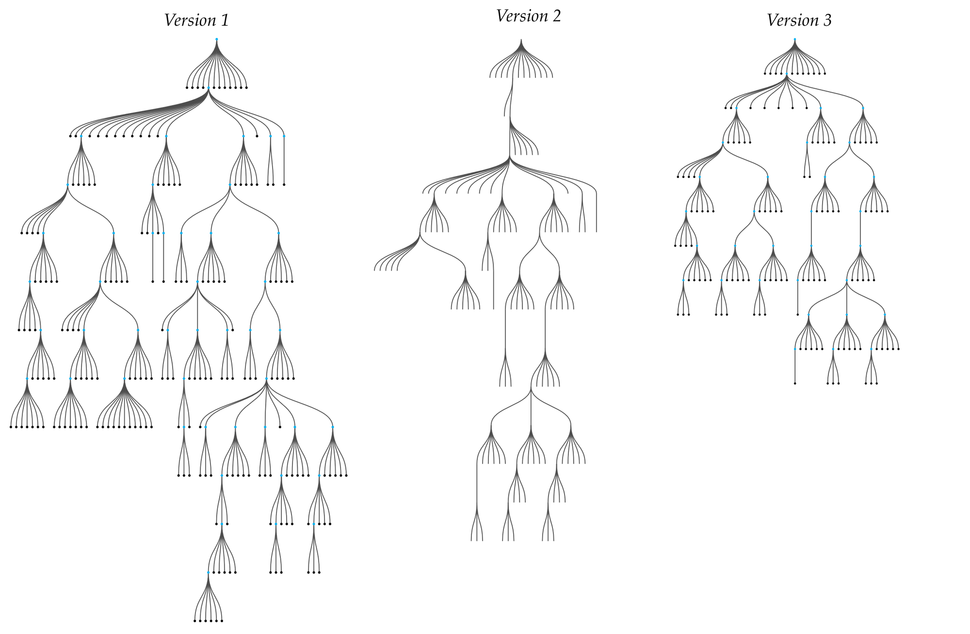
Figure 16: Evolution of the ggIFCGrid object representation: the right hand side version is the original, whereas the left hand side version is the optimised version.
Further refinement, authored by Jon Mirtschin, on the way IFC objects are specified and subsequently serialised led to an even smaller and more efficient representational value of the ggIfcGrid (see above in Figure 16). It is important to note that this strategy relies on Speckle’s serialisation and deserialisation routines that produce SpeckleAbstract objects, nevertheless there is custom application specific code needed for embedding the IFC objects back into Revit that is handled by the GeometryGym toolkit, and masks extra complexity.
4.2.4 Affordances and Limitations
The approach proposed in this section, namely that of programmatically matching strict, well-defined object models with the previously created composable object schema, is highly dependent on how the target object model has been authored. Specifically, the two most important metrics that affect the behaviour and size of a SpeckleAbstract object are a) the depth of inheritance and b) the class coupling.
Depth of inheritance (DI) is a measure that captures the “maximum length from the node to the root of a tree” (Chidamber and Kemerer, 1994). In other words, it measures how much classes inherit from each other. For example, if one has a class called Car that inherits from a more generic one, named LandVehicle, which in its turn inherits from the even more generic TransportationMean, the object model will have a DI factor of three. Chidamber and Kemerer posit that the higher the DI factor of a class, then
- the more methods it is likely to inherit, thus making it less predictable,
- the greater the design complexity (negative), and
- the greater the potential reuse of inherited methods (positive).
The second metric, class coupling (CC), assesses how interwoven—or interdependent—a given object model is. It does so by averaging, throughout the codebase, how many secondary classes one class is dependent upon. As such, for example, if the Bar class contains properties defined from three different other classes, it will have a score of three. While the previous measure is ambivalent, class coupling is seen as a negative property—the higher the measure, the lower the quality of the code (Chidamber and Kemerer, 1994) due to the potential for error. The table below presents the analysis results from Microsoft’s CodeMetrics software on the BHoM (The Buildings and Habitats Object Model, 2019), GeometryGym IFC (GeometryGym OpenBIM IFC, 2019) and IFCKit, BuildingSmart’s official C# implementation and specification of the IFC standard (IFC Documentation and Toolkit, 2019) (Figure 17).
| Depth of inheritance (DI) | Class Coupling (CC) | |
| BHoM | 3 | 51 |
| ggIFC | 11 | 1132 |
| IFCKit | 9 | 693 |
Figure 17: Comparative table showing the depth of inheritance and class coupling metrics for three existing object models.
From the table above, one can see how the IFCKit object model has a lower overall complexity as compared to ggIFC. Nevertheless, ggIFC is much easier to use than the standard IFCKit implementation: the difference in depth of inheritance can be attributed to additional user-facing functionalities, such as accessible object constructors and extra serialisation routines that support multiple protocols. The BHoM object model, being smaller in size and scope, scores much lower than the other two and consequently lends itself much easier to the approach presented in this section. The two IFC-derived object models, due to their DI, and especially, their CC score, generate large, unwieldily and needlessly complex objects that, while still machine readable, not particularly fit for human apprehension.
Class coupling can be tied to one of the biggest critiques of object-oriented programming. Joe Armstrong, creator of the programming language Erlang, famously stated that “[…] the problem with object oriented languages is they’ve got all this implicit environment they carry around with them. You wanted a banana, but what you got was a gorilla holding the banana and the entire jungle.” (Seibel, 2009) This issue was clearly visible in the early tests of encoding ggIFC objects, and the refactoring effort that its author undertook was directed at minimising and managing the class coupling of the object model so that its encoding and decoding to and from Speckle became feasible.
This observation is confirmed by an empirical analysis of the data aggregated in the experimental Speckle server, Hestia, which was made freely available as part of the living laboratory context. Out of 152,200 SpeckleAbstract objects in total, derived from a total of 24 unique object models, the table below compares the average tree depth[17] and size (expressed in bytes)[18] of the existing 2,026 ggIFC-derived and 5,769 BHoM-derived objects (Figure 18).
| Count | Average Tree Depth | Average Size (bytes) | |
| BHoM | 5,769 | 6.03 | 2,935.00 (~3kb) |
| ggIFC | 2,026 | 16.93 | 36,161.99 (~36kb) |
Figure 18: Comparative analysis between the average tree depth and size of BHoM- and ggIFC-derived SpeckleAbstract objects.
The table above reveals that BHoM-derived objects have a much lower average tree depth and size compared to ggIFC-derived objects. The average tree depth of IFC based objects is approximately three times larger than that of BHoM based ones (16.93 vs. 6.03). This has an important cognitive implication on the process of ontological revision: as mentioned previously, the shallower a data structure is, the easier it is for an end-user (developer or, in other cases, designer) to iterate and improve upon it. Lastly, there is a striking difference in the average size of objects: ggIFC-derived instances are, on average, 12 times larger than BHoM-derived ones. This difference in size, when extrapolated to more extensive usage scenarios, leads to potential huge savings in overall storage size.
While the tests based on the IFC object model yielded mixed results, BHoM, and Pegasus are examples where this second approach demonstrated the viability of programmatically matching the flexibility of generating “on-the-fly” schemas with the properties of a formally predefined schema. The main difference being that, instead of having the user manually create custom object properties, these would be automatically instantiated from a given schema definition. Summing up, this proves that a composable object model can, programmatically, lend itself to both end-user “improvisation”, which facilitates a faster rate of ontological revision, as well as a pre-defined fixed schema which satisfies the different need of consistency throughout the design process at later stages.
4.3 Comparative Analysis of Data Structure Sizes
Within the database of the Speckle server Hestia, there are, at the time of writing, approximatively 16,834,814 objects[19]. Based on this data set, an empirical analysis has been conducted that allows us to assess the structure and size of the objects resulting from real-life usage of Speckle. The table below shows the average tree depth and object size of three distinct object categories: (1) abstract objects, derived from existing ontologies, (2) objects with user defined ontologies, and (3) all other objects (not abstract, and with no user defined properties). For reference, the statistics from the previous figure regarding BHoM- and ggIFC-derived abstract objects are replicated in the last two rows (Figure 19).
| Count | % of total | Average Tree Depth | Average Size (bytes) | |
| Abstract Objects | 152,220 | 0.90% | 3.43 | 7,738.27 (~7.7kb) |
| User Objects | 3,099,435 | 18.41% | 2.97 (1.97) | 1,095.45 (~1.0kb) |
| All others | 12,340,793 | 80.68% | 1.42 | 4,523.29 (~4.5kb) |
| BHoM (Abstract) | 5,769 | < 0.01% | 6.03 | 2,935.00 (~3kb) |
| ggIFC (Abstract) | 2,026 | < 0.01% | 16.93 | 36,161.99 (~36kb) |
Figure 19: Comparative analysis table of object depths and sizes.
The most striking finding is the overall high percentage of objects with user-defined properties (18.41%). This suggests a strong user inclination towards engaging with custom data structures and reinforces the hypothesis that revision on an ontological level is crucial. This observation can be partly biased: the creation of such objects is currently facilitated by only two Speckle plugins, catering for Grasshopper and Dynamo, which were, for a long time, the only ones available. These two visual programming software are primarily used by knowledgeable “power users” who are prone to customising available toolsets. Nevertheless, it proves that ontological revision is a key aspect of design communication: almost one in five objects have been customised by end users.
User defined objects (as described in Section 4.1) have an average tree depth value of 2.97. This value takes into account the host object, as well as the properties filed that the user customised. Consequently, the average depth of the exclusively defined by an end user is 1.97 (subtracting the one hierarchical level given by the base object). This informs us with regards to the nature of the process of ontological revision from purely the end-users’ point of view: complex, deeply nested structures (with higher average tree depths) are shunned in preference for shallower, more flat hierarchies of data (with lower overall tree depths).
Coupled with this finding is a distinct reduction in the average size of objects: those derived from pre-existing ontologies tend to be 7 times larger than those defined in an ad-hoc manner by end-users (7.7kb for Abstract objects vs. 1.0kb for user-defined objects). The overall average size of an ontologically derived object is 4.5kb, four times larger than the average user defined one. Consequently, this results in a leaner communication volume, and important savings in storage. These findings have an important bearing on the way data is classified and transacted (discussed in Chapter 5, Data Classification, and Chapter 6, Data Transaction, respectively).
The table below provides an overview of the type of base objects that were customised by end users (Figure 20). It shows that, for example, only 172 Box type objects have been enriched with custom information, as opposed to 847,632 Mesh type objects and 1,310,233 Point type objects. Followingly, this analysis continues by further comparing the number of customised objects against the overall count of that object’s specific type from Hestia’s database.
| Enriched Count | Overall Count | % Enriched | |
| Plane | 25 | 71,949 | 0.03% |
| Box | 172 | 177,594 | 0.10% |
| Circle | 647 | 43,141 | 1.50% |
| Polycurve | 2,474 | 67,831 | 3.65% |
| Object | 15,612 | 15,612 | 100.00% |
| Ellipse | 44,136 | 49,498 | 89.17% |
| Arc | 96,740 | 254,591 | 38.00% |
| Curve | 125,795 | 173,810 | 72.38% |
| Brep | 215,015 | 818,745 | 26.26% |
| Polyline | 217,082 | 793,989 | 27.34% |
| Line | 223,872 | 4,968,801 | 4.51% |
| Mesh | 847,632 | 1,517,236 | 55.87% |
| Point | 1,310,233 | 6,064,101 | 21.61% |
Figure 20: Table representing the number of object types that have been customised by end users.
By actual volume, Points are the most customised object type present, followed by Meshes and Lines. Nevertheless, by percentage out of the overall count of an object’s specific type, Ellipses, Curves, Meshes, Arcs and Polylines all surpass Points: these geometrical “atoms” were used in a more exclusive manner, specifically in specialised workflows. From live observations of the usage of Speckle in practice, ellipses, nurbs curves and arcs are used in bypassing a major interoperability hurdle, namely that amongst free form volumetric NURBS objects and, furthermore, they were often the base upon which complex geometry was rationalised for manufacturing or other later design stages.
The outlier by percentage, the Object type, is explained by the fact that it exists purely as blank slate for end users to create their custom ontologies; therefore, all of its instances are, by default, ontologically enriched.
Lastly, this table helps corroborate the previous affirmation regarding the nature of ontological revision in the design process. The Point type is arguably the most basic 3D structure one can employ in design; similarly, the Mesh type is the least complex volumetric representation. These two types alone account for over 60% of the ontologically enriched objects by volume, confirming the bias against deeply nested data structures, and for simplicity, in communicative design exchanges.
4.4 Managing Ontological Diversity
One of the major limitations of the composable object model discussed in Sections 4.1 and 4.2 is its limited usability outside a programmatic context, such as either code, scripts or a visual programming environment. In Grasshopper, or a script, the end user can control and define, or map, the relationship between object types and their intended native manifestation in the design software. Nevertheless, in a much more common scenario, where not only does the end user not possess programming knowledge, and, moreover, the only tools at hand are the host CAD application’s user interface, defining the conversion logic between schemas is not possible.
So far, the analysis from this chapter has assumed the end user to be both the producer and the consumer of new object ontologies. Nevertheless, because of the difference of skills involved between operating in a programmatic context and the “standard” one, a differentiation between two categories of users is needed: first, the developer of a schema, and second, the consumer of a schema. While the latter is a skilled technician, he does not possess the programming knowledge needed for defining translation routes between object ontologies that the former has. Gantt and Nardi highlighted this dynamic in their paper “Gardeners and gurus: patterns of cooperation among CAD users“ (1992) and studied how “local software developers” package the code their write for the consumption of their colleagues and the distribution within their companies. Consequently, when defining object ontologies, a developer must be able to, if so needed or desired, package them with their “translation” rules for the various applications in use throughout the AEC industry without regard of, or at least minimising, the limitations of the specific software and skills of the end-user. These concerns, coupled with the technical affordances of the .NET platform, have defined the overall software architecture that underpins Speckle’s approach to managing ontological diversity.
4.4.1 Architecture
To formalise this approach, Speckle coined the idea of a “SpeckleKit”: a packaged object model with a set of translation routines to and from the software applications it is meant to support. In a metaphorical sense, a “SpeckleKit”, can be seen as a glossary containing a set of conceptual definitions, as well as several independent dictionaries that “explain”, or translate, said concepts in various different languages (Figure 21). Specifically, one can examine the CoreGeometry[20] kit, which groups together the basic geometry types and primitives that have been listed previously in the 4.1 Composable Data Structures section: It consists of the following separate sections:
- A set of class definitions (“the glossary”, containing definitions for the Boolean, Number, String, Interval, Interval2d, Point, Vector, Plane, Line, Circle, Arc, Ellipse, Polyline, Curve, Polycurve, Box, Mesh, Extrusion, Brep objects),
- A partial set of conversions methods for Dynamo (“a dictionary for the dynamo language”),
- A partial set of conversions methods for Revit (“a dictionary for the Revit language”),
- A full set of conversions methods for Rhino and Grasshopper (“a dictionary for the Rhino language”)
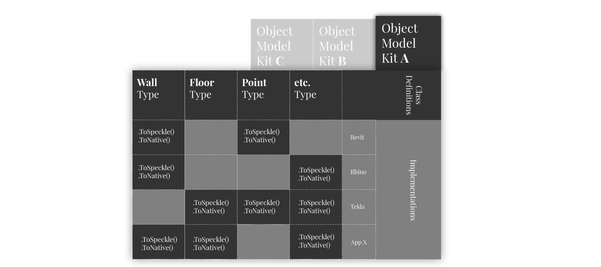
Figure 21: Table view of an imaginary object model kit, which shows the demarcation between the class definitions and their actual conversion implementations in separate CAD software applications.
Multiple kits can coexist and build on top of each other. At the time of writing, two more kits have been developed independently of each other: the first, “SpeckleElements”[21] adds a set of basic higher-level architectural objects, namely Wall, Floor, Beam, Column, Level, and Grid. As its geometric base, it uses the CoreGeometry kit, and presently contains translation logic only for the Revit software application. The second, “SpeckleStructures”, is a closed-source kit developed internally within Arup, an engineering and consultancy company, and adds a set of schemas pertaining to the domain of structural engineering (e.g., 1dMember, 2dMember, LoadCase, etc.) and translation logic from Revit, GSA and ETABS[22].
Available kits are loaded dynamically, at run-time, by the CAD application plugins in their execution domain (AppDomain). Thereafter, by leveraging the relevant kit “dictionary”, this allows for the automatic conversion from the native application object model to the one defined in a kit. Similarly, it allows the opposite conversion, from the kit’s defined schema to the native object model. If overlapping kits are present, the current default behaviour is to use the first one loaded, or defer this choice to the end-user.
4.4.2 Conversion Flow
In order to enact the translation between a host application’s object model and the ones present in the various kits, two methods are present: serialise and deserialise. Similarly, the “dictionaries” of a kit must contain, in order to be complete, two methods for each schema they support: the first, by convention named ToSpeckle, encapsulates the logic that takes a native object and translates it into its counterpart present in the kit; the second, again by convention named ToNative, encapsulates the reversed logic. For example, the signature of such a set of functions looks like this:
// Extenstion method for app to kit object conversion
public static KitObjectA ToSpeckle( this NativeObjectA myNativeObject ) { /*…*/ };
// Extenstion method for kit object to app conversion
public static NativeObjectA ToNative( this KitObjectA myKitObject ) { /*…*/ };
Figure 22: (Code Block) Signature of the ToNative and ToSpeckle functions.
The role of the serialise and deserialise methods is to act as a single entry point for object conversion between object models. Specifically, their role is to efficiently search for and match their given input objects to the correct serialisation routines present in the available kits. For example, when the serialise function is called on a given object, it will first investigate its context (the kits loaded in its current AppDomain) and check if the object has a direct conversion method defined (ToSpeckle) in its relevant kit dictionary. If one is present, it will invoke it using reflection, and return the result. Furthermore, these ToSpeckle methods are cached in memory for the duration of the session in order to bypass searching for them again. Nevertheless, if it is unable to find a valid translation method, it will attempt to create a SpeckleAbstract object by reflecting on all the properties that the original object, as described in the previous section (4.2 Encoding Existing Ontologies).
The deserialise routine follows a similar logic path with the serialisation routine presented above (see the figure below). Upon receiving an object, it will search its existing context for a direct conversion routine for that specific object type (ToNative method). If one is found, it will invoke it and finally return the result of the invocation. If no ToNative methods are found, it proceeds to look if the type of the given object is SpeckleAbstract. If it is not, there is nothing it can attempt to do further; as such it returns the original object, unchanged. This can be considered a failed attempt at deserialisation; nevertheless, no errors are thrown as there are contexts where this behaviour can be considered valid. Otherwise, if the given object is of the SpeckleAbstract type, it will proceed to try and deserialise this to its original type.
4.4.3 Symmetry
One of the limitations of this approach is the fact that one cannot assume identical contexts across the design process: different actors and stakeholders may or may not be in possession of the kits (schemas and their implementations), or a specific object type has no representation in another application. The former case is possible because, for example, some companies may choose to not share a kit that they developed – as is the case with SpeckleStructures, developed by Arup and not distributed externally. The latter setting is also a common occurrence: while the Wall object may exist in Revit and other drafting software, it does not exist in Rhino or other modelling applications, or, for example, NURBS surfaces, while present in Rhino, do not have an equivalent in Blender, or SketchUp. Consequently, an object created in one context may fail to be understood in another one.
Specifically, there are three possible scenarios: given two different contexts, A and B:
- Fully shared context: A and B contain the same kits,
- Partially shared context: A and B share only some kits, but not all,
- No shared context: A and B do not share any kits.
In the case of (1), an object originating from context A will be understood in B. In other words, the serialise and deserialise functions are symmetric:
myObject == deserialise( serialise( myObject ) ) // evaluates to true?
In the case of (2) and (3), the above statement evaluates to false. In the case of (2), the deserialise method will attempt to degrade gracefully. Concretely, it will look for the types that a given object inherits from in reverse order of abstraction, and for each of those types tries to find a ToNative method valid in its given context. This approach allows for a “lossy” interoperability process, and is particularly useful in many scenarios. For example, when translating between Revit and Rhino a wall object, even if Rhino does not have a native object supporting such an object, the deserialise method will be able to return a mesh object with several converted sub-properties, such as base line and thickness, specifically because, in this example, wall inherits from mesh. This enables various stakeholders to partially understand each other’s data, and thus enables their coordination.
Summing up, one must not assume that the serialise and deserialise routines are symmetric. Similarly to the popular whispers (apocryphally Chinese) game, the process of ontological revision introduces a certain mutability in the flow of data. This has an important bearing on the issue of consistency, and specifically object identity: if an object changes by being interpreted in different contexts, how can one avoid the issue of data and fidelity loss? The way this limitation is mitigated is presented in Chapter 5, Data Classification, where an important feature of the whole communication framework, namely unique hashing and immutability, is introduced.
4.5 Conclusion: Enabling Ontological Diversity
The proliferation of informal standards may be seen as detrimental to the consistency required in the digital design and construction process. Nevertheless, so far, consistency has been wrongly equated with rigidity, by virtue of the fact that existing formal approaches rely almost exclusively on the IFC standard, whose stated aim is to be the single source of schemas describing all of the built environment’s constituent objects.
This chapter has introduced a new approach to managing and specifying digital data representation, one that is primarily emphasising composability and that aims to enable, rather than dissuade, the act of ontological revision that various stakeholders must embark upon in order to streamline their communicative processes.
Followingly, this approach has been evaluated in three different contexts. First, Section 4.1, Composable Data Structures looked at how end-users created and evolved their own ontologies, or “ad-hoc” object models, for the purpose of exchanging information across disciplinary boundaries. Second, the affordances of programmatically matching the composability of the lower-level approach with existing, higher-level standards has been evaluated in Section 4.2, Encoding Existing Ontologies. Third, in Section 4.3, Managing Ontological Diversity, the investigation focused on what would be the best way to enable multiple object models within a digital design communication process. Succinctly put, the findings can be summarised as follows:
- A lower-level, composable object model enables a productive process of ontological (representational) revision, as evidenced in Section 4.1.2. Section 4.3 reveals that 18% of the total objects transferred by Hestia, the test Speckle server, have been enriched with custom structures by end-users.
- Existing higher-level object models from the industry, such as BHoM (Section 4.2.2), as well as IFC (Section 4.2.3), can be natively supported, thus allowing for “backwards-compatibility”.
- Further, Section 4.3 reveals that end-user driven ontological revision tends to minimise the complexity of the data structures involved (an average tree depth of 1.97, as opposed to 3.43 for pre-existing schemas). Moreover, there is strong evidence as to the preference for base “geometric atoms” when custom schemas are articulated. This also results in a leaner communication volume, as average user-created object sizes are approximatively seven times smaller than ones derived from existing ontologies (1kb vs 7kb), and four times smaller than the overall average (1kb vs 4.5kb).
- The reduced complexity of data structures allows for more user inference to manifest at the receiving end, and subsequently requires more user intent from the sender.
- The programmatic tests from Section 4.4 demonstrate that multiple, self-contained object-models can be programmatically supported in a simultaneous and consistent manner in a digitally enabled design communication process, thus invalidating the industry’s assumed need for a singular, unique object model.
In short, the ontological richness and diversity of the AEC industries, rather than being suppressed, can be embraced and supported in a productive way by current technical affordances. As Sperber and Wilson remark about natural (social) communication processes (Wilson and Sperber, 2008), information exchange in the digital design context tends to follow a path of least resistance by maximising the relevance of the input and minimising its complexity.
Lastly, by being codified and decoded in different contexts, information changes throughout the process of communication. The approach described in this chapter suffers from a similar limitation: because one cannot provide a guarantee as to the availability of shared object models between these domains, one cannot guarantee a symmetrical behaviour of the codification and de-codification functions (serialisation, deserialisation). This is a major implication that will be specifically tackled by the following chapter, Data Classification.
Footnotes
[11] The full implementation is available online at the following link (accessed 2nd June 2019).
[12] Collisions may occur after storing an excess of 2^64 hashes, or 18,446,744,073,709,600,000.
[13] At a cursory glance, data gathered shows more than 20 different unique object models.
[14] The full code is available here (accessed 2nd June 2019).
[15] This number is, in programming lingo, a magic number. In other words, it has been chosen heuristically according to observed behaviour (allowing for a reasonable amount of depth, but protecting from too nested objects), but it is not supported by evidence and does not imply code safety, correctness or utility.
[16] In a later implementation, this limitation is removed by relying on an array that kept track of previously processed objects. Simply put, if a previously processed object is encountered, the respective branch is no longer followed.
[17] The tree depth of an object is obtained by calculating the maximum nesting levels of its properties.
[18] The object’s size was calculated by measuring the byte array length resulting from its JSON representation.
[19] At the time of review, circa two months later (October 2019), there currently are 20,795,069 objects. At the time of submission (August 2020) this number exceeds 40 million.
[20] Full code available here (accessed 8th of June 2019).
[21] Full code available here (accessed 8th of June 2019).
[22] GSA and ETABS are structural analysis software.